 Introduction:
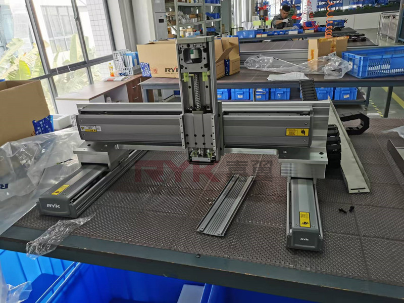
We often hear terms like linear modules, slide modules, and linear slides—these all refer to linear motion modules, a key component in industrial automation. These single-axis systems can be combined into multi-axis Cartesian robots (e.g., XY gantries, cross configurations) for diverse applications.
At RYK Technology, a leading manufacturer of precision linear modules, we offer:
- High-accuracy ball screw modules: RY series (semi-enclosed) and RY-FB series (fully enclosed).
- Ultra-precision linear motor modules: RY-Z series.
Need help selecting or installing a linear module? Below is a detailed guide. For personalized support, consult our engineers.
Step 1: Platform Requirements & Preparation
- Stability Matters: The installation platform must withstand high dynamic forces. Insufficient rigidity causes vibration/resonance, reducing accuracy and lifespan.
- Flatness Standards: Ensure platform flatness is ≤0.05mm/500mm (standard) or ≤0.02mm/500mm (high-precision apps). Poor flatness deforms导轨 (linear guides), accelerating wear. (Learn more about linear guide maintenance.)
- Clean Surface: Remove debris or burrs before installation.
Step 2: Single-Axis Module Installation
Option A: Top-Mounting
- Remove dust covers. Secure module via base holes using hex screws (M6/M8 per specs).
Option B: Bottom-Mounting
- Thread screws upward through the platform into the base.
⚠️ Critical: Use manufacturer-specified screw lengths.
- Too short: Weak clamping → slippage.
- Too long: Interferes with sliding parts → damage. (For screw torque guidelines, see ISO 898-1.)
Step 3: Motor Installation
For servo/stepper motors:
- Direct Coupling: Align motor flange with ball screw axis.
- Belt-Driven: Sync pulleys must align within ≤0.5mm.ll
- Tighten couplings securely, then reattach covers.
(Pro Tip: Match motors using our compatibility tool.)
Step 4: Sensors & Power-On Test
- Install limit switches in side slots. Optional: Add cable carriers (Igus offers durable solutions).
- Test run: Check for abnormal noise/movement before precision validation.
Step 5: Optional Accuracy Verification
Method A: Horizontal Parallelism
- Fix module to a granite table. Use a dial gauge on the slider. Align to a reference straightedge; max-min deviation = parallelism error.
Method B: Vertical Parallelism
- Measure against a precision surface. Record dial gauge fluctuations.
(Note: Factory-tested modules rarely need recalibration. For advanced metrology tools, visit Mitutoyo.)
Final Notes
Single-axis modules arrive pre-assembled (motors/sensors included)—just bolt and go! Multi-axis systems require guided assembly.
Need a custom solution? Contact RYK Technology today!
📞 Sales Team | 📧 [email protected]

